
But a modem wouldnt hang up on call waiting for my brother who lived in a different area, and a year later, didnt work for me either. I had been taking advantage of older telephone company equipment that needed to break the circuit to insert the call waiting tone. It was the break and not the tone that hung up the modem. But Id gotten used to squatting indefinitely on the internet without fear of missing an incoming call.
Eventually I realized that recognizing the tone and hanging up the modem could be performed automatically by an electronic device. In fact, this function is available commercially in stand-alone products. More recently, this feature has been integrated into some modems. My brother found another solution: a cable modem that doesnt use telephone lines at all.
I was looking for something more educational, and I had access to a retired telephone engineer, Steve Flocke. Much of the problem could have been solved with a specialized telephone tone decoder chip, but that seemed too much like buying the answer. And the digital part of the problem could have been solved with a microcontroller, but I wasnt looking for a software project.
Instead, this became an analog electronics project built of ordinary components. And if you hadnt guessed, the name of the project is the hip answer to the question of disconnecting the modem: Internet? Internot.
The call waiting tone is 440 Hz for 300 ms. This needs to be distinguished
from other signal tones and modem communication. It might be nice
to distinguish from speech as well, but this isnt really worth the trouble.
Disconnecting the modem is simple, but best done with a relay so the unit
can safely stay in circuit with power off. With the relay disconnecting
the modem only and not the voice telephone, there is no harm in a false
trigger disconnecting the modem during voice communication.
| Signal | Frequencies
(Hz) |
Power
(dBm/f) |
Duty Cycle |
| Dial Tone |
350 + 440
|
-13
|
|
| Busy |
480 + 620
|
-24
|
½ sec. on, ½ sec. off |
| Auxiliary Ring |
440 + 480
|
-19
|
2 sec on, 4 sec off |
| Call Waiting |
440
|
-13
|
300 ms on, 10 sec off, 300 ms on |
| Data Set Answerback |
2025
|
-13
|
|
|
from Notes on BOC-IntraLATA Networks 1983 by Central Services
Org.
|
|||
Besides the well known telephone signals from the system, there are numerous modem protocols, including an especially troublesome tone during the initial negotiations between 56k modems. Identifying call waiting can be done by any reliable strategy that may exploit both frequency and duty cycle (or pulse width). Detecting frequency well would require many sharp filters. Pulse width offers an easier target. Call waiting is an unusually short signal.
The input to these detectors comes from the phone line, so there is circuitry to protect the unit and the phone system from each other. This doesnt leave enough for the detectors to work with, so first the strength of the signal is greatly enhanced with an amplifier and filter.
When a signal comes out of the pulse detector, it means call waiting is recognized, and though this signal may be brief, disconnecting a modem may take some time. Fortunately, the phone system is very quick to recognize when the circuit is opened by relay, and the telephone rings within a few seconds. The modems in computers seem a lot more patient, so a timer is needed to lengthen the disconnection signals duration to about ½ minute.

When the relay is off, little power is used, so the unit can be left powered up forever, which means the power supply will go unattended and needs to be safe, so dont invent your own. The biggest opportunity to save money and your life is to scrounge a commercial DC power pack of at least 7.5 volts and enough milliamps to drive the relay. Note that the connectors usually have ground on the inside. Some power packs arent filtered, and if you dont have an oscilloscope, the only symptom may be untraceable strange behavior, so add a big filter capacitor if in doubt.
The LM7805 is the generic voltage regulator that takes its input voltage from pin 1, burns up whats not wanted, and puts the regulated 5 volts on pin 3. Remember that the wattage through the regulator is basically due to all the voltage youre throwing away: the input voltage minus 5 times the amperage through the circuit, which is mostly the amperage needed for the coil. So if you did something silly like get a 24 VDC power pack and 100 mA relay coil, then thats 1.9 watts, and youd be in more trouble on the regulators wattage than voltage.
The power supply section includes a bypass capacitor because the unit includes digital circuitry that puts sudden demands on the supply. The green LED lights when power is on.
Telephone connectors are usually called modular connectors or more formally RJ-11. The middle two wires are red and green. The relay must be double-poled, breaking both lines when activated, to prevent an imbalanced line which sounds like noise. The contacts need to tolerate high voltages because they are directly on the phone lines.
The phone interface is not a good place to cut corners. Your circuit needs to be protected from lightning strikes and the phone company needs to be protected from your circuit. So the telephone audio input section is high voltage and heavy attenuation. The series capacitors isolate you from DC, especially the ring voltage. The series resistors attenuate the remaining AC. The parallel capacitor protects you from spikes. The transformer provides more isolation. This is an audio frequency transformer whose impedance isnt very important. Finally, the back-to-back 1N4733A 5V Zeners mean to limit the voltage out of this section to ±5V. Any Zeners can be substituted, preferably low voltage and high wattage. This section in particular is courtesy of Steve Flocke, retired phone company, which is an acknowledgment and not an endorsement, but may be as close as youre going to get to happy interfacing with the phone company.

A signal near 440 Hz (the center frequency) will be amplified by a factor 100 (the gain). The gain depends on all the earlier components and its purpose is to get enough signal to the LM567 in the frequency detector section. The bandwidth is 44 Hz, which is 440 Hz (the center frequency) divided by 10 (Q, the quality factor). The only frequencies appreciably amplified are those in this band, 418 - 462 Hz, in other words, 440 Hz ± 5%. Since the components that determine the center frequency are 5% tolerance, a Q of 10 is as high as it can be without risking that the filter rejects the intended frequency because the components were out of tolerance.
This design comes from the book by Horowitz and Hill titled The Art of Electronics (1989), Figure 5.19. The design is both over my head and easy to use, and makes good use of one good IC. The LM324 is easy to get and needs only a 5V supply. For the op-amps in this circuit, the reference voltage is 2.5 V. The four op-amps are interchangeable.

The input is coupled through the 0.1µF capacitor. The output of the LM567 is an uncommitted transistor collector, so is pulled up through the single resistor to 5V so the output is normally 5.0 V. When the frequency is detected, the output is 0.0 V, and the yellow LED lights.
This design comes from the LM567 data sheet. The LM567 is a tone decoder especially for the telephone keypad. This is the most uncommon IC in the entire design, but not hard to get.
The integration and differentiation are carried out on the input, which has only two levels, so these operations are relatively simple. The 10 µF capacitor accumulates voltage for the integrating op-amp. When the input is high (5.0 V), the output of the integrator ramps down. When the input is low (0.0 V), it ramps up, but more quickly because of the larger difference from the integrators reference voltage (3.5 V). Of course, if the input remains unchanged, eventually the integrator output will level off. Within these limits, the integrators output voltage is proportional to the duration of the input pulse.
The 0.01 µF capacitor passes voltage changes for the differentiating op-amp. When the input changes between its two levels, the differentiators output pulses quickly, so this signals that the input pulse has ended. When the input transitions high to low, the differentiator pulses quickly high then low then levels off. When the input goes low to high, the differentiator pulses low then high then levels off. The differentiators reference voltage is also very high (3.5 V), so its output is normally high and only the low pulse appears.
The input is normally high and the integrator output near zero. When the frequency is detected, the input goes low, and the integrator begins to ramp up. After 300 ms, the integrator output is above 1.0 V but still below 2.0 V. The integrator output is compared with each of these limits. One comparator op-amp outputs low when the integrator is above 1.0 V, and the other comparator outputs low when the integrator is below 2.0 V.
The comparators and differentiator outputs combine in a voltage adder at this sections output. The op-amps are arranged to output at saturation, so have only two output levels, zero and about 3.5 V. So this sections output is about (3.5 × n + 5.0) / 4, where n is the number of op-amps outputting high. If all op-amps output low, then the sections output is about 1.25 V; otherwise it is at least 2.125 V. The LM555 in the timer section always triggers when its input is below 1.45 but never when above 1.9 V. So the trigger occurs when three conditions are true simultaneously: the pulse is long enough, the pulse is short enough and the pulse has changed (ended).
In theory, and without the 220kW resistor, the integrator should ramp up at 1 / (100kW × 10 µF) × 3.5 V = 3.5 V/s, and cross the 1.0 V and 2.0 V thresholds at 290 ms and 570 ms. And it should ramp down at 1.5 V/s. In practice, the extra resistor is needed and the ramp rates are more like 5.0 V/s up and 1.0 V/s down. The output of the differentiator, in theory, should have no pulse width at all, but with the components used is on the order of 1 ms.
An interesting characteristic of this design is its symmetric treatment of high and low input voltage levels. The asymmetries are the ramp rates and comparator thresholds which are the result of the reference voltages in the voltage divider. So this section not only detects on pulses, but also would detect off pulses of relatively long duration. However since the 440 Hz call waiting frequency is relatively rare, such off pulses do not appear. The advantage of this symmetry is its tolerance for noise. If the input shuts off temporarily, the pulse detector does not completely reset. This helps preserve legitimate signals even if the frequency detector briefly fails to detect them, and helps discard signals that are too long, even if they are slightly discontinuous. This last condition occurs in the initial negotiations between 56k modems, and was the nemesis of an earlier, more digital design.
This design uses an LM324, which is easy to get and needs only a 5V supply. The op-amps in this circuit use the reference voltages to their best advantage. The output voltage range is 0.0 to 3.5 V. The four op-amps are interchangeable.
On power-up, the 0.1µF capacitor charges slowly through the voltage divider. Attached to pin 4, this provides at least 10 ms for all sections of the unit to stabilize before the trigger is enabled.
When the output is raised, the red LED lights and the transistor sinks to ground the coil current of the relay in the phone section.
This design comes from the LM555 data sheet. The LM555 is very easy to get. The input triggers never above 1.9 volts and always below 1.45 V, a detail exploited by the voltage adder of the frequency detector.
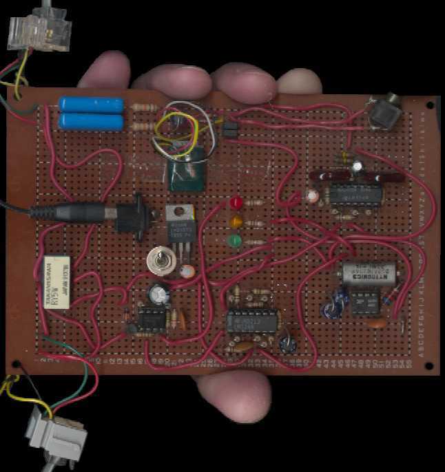 |
| Photo of a unit built on a PC board: LEDs (center), power input (left), phone jack to wall (upper left), then following the signal path clockwise around the board: phone input, amplifier & filter, frequency detector, pulse detector, timer, phone jack to modem (lower left), and relay. |
I built some of mine on a breadboard before transferring it to PC board. Build yours any way you want.
The place to tap the circuit is between the phone and amplifier sections. I mounted a phono jack at this spot on my board and ran a cable to my PCs stereo microphone input jack. Thats all you need to start recording tone samples (and entire phone calls if youre Linda Tripp). Then you can play back samples through the rest of the board using the same jack. But try to avoid connecting two outputs together even temporarily. Unplug the phone line and connect the phono jack tap to the speaker line out of your PC. Youll need to adjust levels and will want to listen as the sample is playing. I connected the line to one of my stereo speakers through a big resistor to the board, so I was able to hear the sample through the other speaker and could adjust the level with the speakers volume knob.
Finally, you need a way to calibrate. If you record call waiting
tone samples and a dial tone sample under the same conditions, then you
can use the dial tone as your reference. Disconnect the playback
setup, plug in the phone line and tap the circuit between amplifier and
frequency detector and watch that on an oscilloscope or just use an AC
volt meter. Measure a real dial tone. Now leave the scope or
meter attached and go back to the playback setup, play your dial tone reference
sample and adjust the volume to match the real dial tone. Now you
can play back the call waiting samples knowing they are at realistic levels.
 |
| Oscilloscope image of a dial tone as seen at the amplifier output of a typical unit. 5 ms/div horizontally, 200 mV/div vertically. |
Another interesting place to put an oscilloscope probe is at the output of the integrator of the pulse detector. From the integrator, the output of the frequency detector can be inferred: the integrator voltage rises when the frequency is detected, and falls (at a slower rate) otherwise. The behavior of the pulse detector can be inferred also: visually compare the integrator with the reference voltages of the comparators and expect that the differentiator will fire when the integrator changes direction. The pulse detector output fires if the integrator changes direction while between the two voltages. And if these claims are borne out in reality, then the testing is finished.
Except for the dial tone, no long signals of about 440 Hz occur during modem communications, except during about one second of the initial contact between 56k modems and this varies somewhat by model. One such troublesome signal turned the frequency detector on for 500 ms, off for 125 ms then on again for 375 ms. In a typical unit, the integrator output reaches its lowest level at about 0.2 V. With a 500 ms on pulse from the frequency detector and a 5 V/s ramp rate, the integrator reaches 2.7 V. Followed by 125 ms off at 1 V/s, leaves the integrator at about 2.6 V, and the final 375 ms on runs the integrator up until the op-amp saturates at about 3.8 V.
With these parameters, a tone reaches 1V after 160 ms, and 2V after
360 ms.
 |
| Oscilloscope image of a troublesome signal as seen at the output of the integrator of the pulse detector of a typical unit. 1V and 2V thresholds are also included. 100 ms/div horizontally, 1 V/div vertically. |
If you want to see whats going on, there is the traffic light style series of LEDs: green means the unit is on, yellow means the frequency is being recognized, and red means the modem is being disconnected. The green, of course, is on all the time, the red is on for 24 seconds at a time, and the yellow is on only briefly unless you pick up the phone and so generate a dial tone, which is a good test. If the yellow seems to flicker or stay on when the modem is connected, youve got noise problems.
The unit will trigger during ordinary voice communications (especially if you speak loud and low) making the relay click. This doesnt bother the unit, but it might bother you if you dont put it in a box. Mine has also triggered occasionally for lightning strikes.